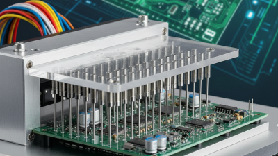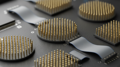
A printed circuit board assembly can look flawless and still fail after hours of heat, vibration, or electrical load. A solder joint may hide a tiny crack. A connector can pass a quick check, then loosen during handling. That is why pcba testing must examine both function and manufacturing quality, not appearance alone. Small defects matter.
This guide explains how visual inspection, automated optical inspection, X-ray inspection, in-circuit testing, and functional testing reveal different risks. Each method answers a different question. Does the board match its design? Are components placed and soldered correctly? Do circuits behave as intended under realistic conditions? The right test plan depends on the product, its operating environment, and the cost of failure. A medical controller and a simple consumer device do not need identical test coverage.
Quality expert W. Edwards Deming is often associated with the principle, “Quality is everyone’s responsibility.” Applied to PCBA, that means reliability begins before the test station: with clear design requirements, controlled assembly, and traceable inspection results. Testing then provides evidence, not a guarantee. A clean test report cannot prove that a board will never fail. That limitation deserves attention, even when production schedules are tight.
The sections ahead outline practical checks, common test equipment, and ways to interpret results. They also consider how to choose coverage without adding tests that provide little value. The goal is straightforward: catch meaningful defects early, document what was checked, and make decisions based on evidence rather than appearance or assumption.
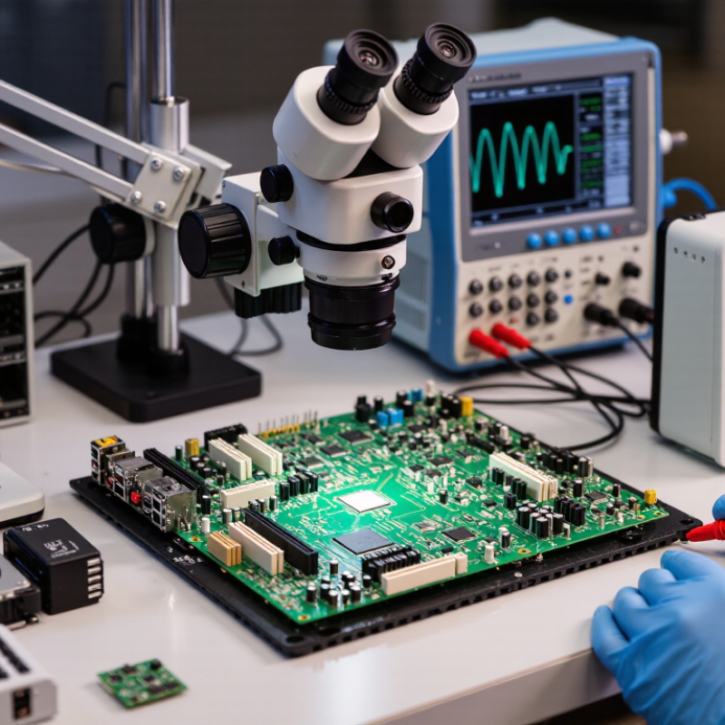
A useful PCBA quality plan starts with a clear definition of acceptable performance. Translate product needs into measurable requirements before selecting tests. Specify electrical limits, such as supply voltage, current draw, signal tolerance, and connector continuity. Set workmanship criteria for solder joints, component placement, and board cleanliness. Use clear pass or fail thresholds. “Works on the bench” is not a requirement.
Reliability requirements should reflect the board’s real operating conditions. Document expected temperature range, humidity, vibration, duty cycle, and service life. A controller inside a warm enclosure may need different screening than a board exposed to frequent handling. Define how long the product must operate and what failure rate is acceptable, where practical. Include startup, shutdown, and power-interruption behavior. Small details matter.
Tie each requirement to a verification method and record the conditions used. For example, define test points, firmware versions, fixture limits, and sampling frequency. Keep traceable records of results and failures. A first-article inspection may reveal placement or soldering issues, while functional testing checks intended operation. Environmental tests can expose weaknesses that a short bench run misses. Be cautious with accelerated testing: severe stress can create failures that normal use would not. Requirements may need revision after field feedback. That is not a flaw in the process; it is evidence that assumptions deserve review.
Before testing, confirm that the assembly matches the current drawing and bill of materials. Check component orientation, connector placement, and visible solder joints under steady lighting. Remove loose debris, but avoid handling exposed pads with bare fingers. Use ESD-safe tools and verify that the test fixture makes firm contact. A loose probe can create a false failure. In practice, fixture checks are sometimes rushed, and that can waste hours.
Choose test methods based on the board’s construction and intended use. Automated optical inspection can catch misplaced parts and visible solder defects. X-ray inspection helps assess hidden joints beneath packages. In-circuit testing can detect opens, shorts, and component-value problems when suitable test access is available. Functional testing checks whether the board behaves correctly under realistic inputs and loads. No single method catches everything. A board may pass inspection yet fail when warm or under load. Record test limits, equipment calibration dates, and failure locations. For early production, examine a few boards closely before relying on sampling; small runs can reveal patterns that a quick pass misses.
Visual inspection catches defects before instruments do. Under magnification, check solder joints for bridges, insufficient wetting, voids, and disturbed components.
Compare polarity marks and component positions with the assembly drawing. Automated optical inspection can flag small placement shifts, but it cannot confirm hidden solder joints.
IPC-A-610 provides visual acceptance criteria; use the applicable product class and documented inspection limits. A pass on appearance alone is not enough.
Electrical testing checks continuity, shorts, and component values. Use in-circuit testing for accessible nets, then a flying-probe or boundary-scan method when fixture access is limited.
Functional testing should exercise the board under realistic input voltage, load, and temperature. Record failures by defect type and lot.
IPC-7912A outlines yield calculations; track first-pass yield as boards passing the initial test divided by boards tested. A rising yield matters, but one clean batch proves little.
Test coverage can also leave blind spots.
Tips: Keep golden-board readings and test limits under revision control. Recheck probes when contact readings drift. Retest repaired boards, and log the original failure; otherwise, the data can hide recurring faults.
Environmental and mechanical tests reveal weaknesses that a visual inspection can miss. Thermal cycling exposes a PCBA to repeated temperature changes, which can stress solder joints, vias, and component connections. Choose temperature limits and dwell times that reflect the product’s actual operating environment. An aggressive profile may create failures that would not occur in service.
Humidity testing can uncover corrosion risks and intermittent electrical behavior, especially around exposed conductors and contaminated surfaces. Monitor the board while it is powered when the test plan allows, and record failures alongside temperature and humidity readings. Keep a baseline sample for comparison. Small details matter.
Mechanical reliability needs attention too. Vibration can loosen connectors or fatigue solder joints; shock testing can reveal weak component support or mounting points. Secure the assembly as it would be installed in the final product, then inspect critical areas under magnification.
A cracked joint may be difficult to spot. Compare electrical test results before and after each exposure, and document the test setup so results can be repeated.
One caveat: a single failed sample does not always prove a design flaw. Fixture setup, handling, or an unusually severe test profile may have contributed, so investigate before changing the design.
A PCBA test report should show more than a pass or fail. Compare measured values with approved limits, then group failures by board revision, test station, and fixture channel. For example, repeated low readings on one connector pin may indicate a soldering issue, a probe contact problem, or both. Check raw measurements and retest records before naming a root cause. A passing retest alone does not explain the original failure.
Tips: Record the board serial number, test step, measured value, limit, fixture ID, and software version. Add a clear photo when a physical defect is visible. Small details matter.
Document corrective actions while evidence is fresh. State the observed symptom, the suspected cause, the investigation performed, and the action taken. Assign an owner and due date, then verify the change using the same test conditions and a suitable sample of boards. If a fixture was adjusted, record that separately from a design or process change. A rushed review can miss this distinction. Teams sometimes label a cause “operator error” too quickly; that answer may hide unclear work instructions or inconsistent contact pressure. Note any unresolved uncertainty, and keep the original failure data with the final record.