Top 10 PCB Test Jigs You Need for Perfect Testing?
In the fast-evolving electronics industry, ensuring the reliability of printed circuit boards (PCBs) is crucial. A recent industry report indicates that the global PCB market is expected to reach $80 billion by 2025, reflecting the increasing demand for high-quality PCBs. This surge emphasizes the need for effective testing solutions, making the use of a PCB test jig indispensable.
PCB test jigs provide precise and repeatable testing environments, allowing engineers to detect faults early. With the right jig, manufacturers can improve their quality assurance. However, many still grapple with the challenge of selecting optimal jigs for different applications. A lack of standardization in testing processes can lead to inefficiencies. Moreover, not every jig meets the specific needs of all PCB designs, leading to potential discrepancies in results.
Investing in the right PCB test jig is not just about following trends; it is about ensuring quality and reliability. As the industry grows more complex, the importance of tailored testing solutions cannot be overstated. Understanding these tools is essential for manufacturers looking to stay competitive in a demanding market.
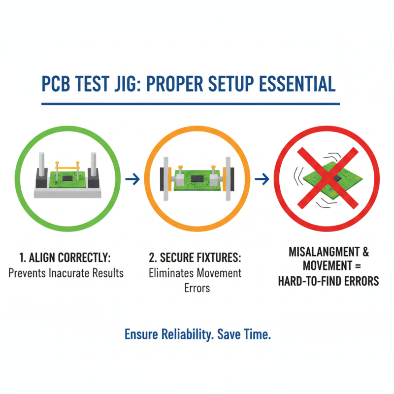
Understanding the Importance of PCB Test Jigs in Electronics Testing
PCB test jigs play a crucial role in electronics testing. They ensure that PCBs are functioning as intended. As reported by research firms, effective testing can improve product reliability by up to 30%. This is significant in a fast-paced market where downtime can cost companies thousands.
A well-designed test jig provides the necessary support for various testing procedures. It allows engineers to access specific components easily. For instance, most jigs incorporate automated testing features. These enhancements lead to quicker evaluations and fewer human errors. However, not all jigs are created equal. A poorly designed jig may result in inconsistent results or damage to sensitive components.
Data highlights that nearly 20% of PCBs fail during the initial testing phase. This indicates a need for refinement in both jig design and testing protocols. Engineers must continually assess their testing setups to identify weaknesses. A focus on ergonomic design and adaptability can lead to better outcomes. Investing time in these areas is essential for maintaining competitiveness in the electronics field.
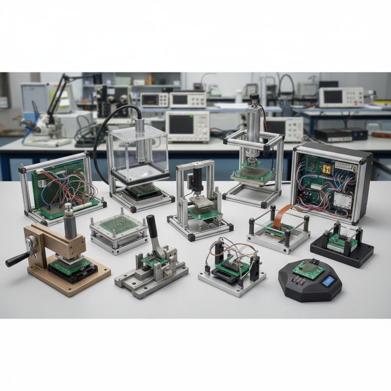
Types of PCB Test Jigs: A Comprehensive Overview
When it comes to testing printed circuit boards (PCBs), several types of test jigs are essential for ensuring accuracy and efficiency. The most common types include fixture-based jigs, bed-of-nails testers, and flying probe testers. Fixture-based jigs provide a stable environment, allowing for precise placement and efficient testing. According to industry reports, companies using these jigs can reduce error rates by up to 30%, illustrating their importance.
Bed-of-nails testers have gained popularity due to their versatility. These devices can test multiple points simultaneously. They are especially useful for high-volume production, as they save time. However, they require accurate programming to avoid damage during testing. A common oversight is neglecting regular maintenance, which can lead to increased downtime.
Flying probe testers are another impressive solution. They utilize robotic arms to probe the circuit directly. This method offers flexibility, but it typically has slower speed compared to others. Reports indicate that flying probe testers can be less effective for high-density boards. Designers need to balance speed and accuracy during PCB development, making the selection of the right jig critical. At the end of the day, the choice of testing jig can greatly influence product quality and production costs.
Key Features to Look for in Quality PCB Test Jigs
When selecting a PCB test jig, focus on key features essential for quality testing. The design should accommodate various PCB sizes. The easier it is to adjust, the better. Many industry standards highlight the importance of adaptability in testing equipment. A report from IPC shows that 70% of manufacturers prioritize flexibility in their testing setups.
Durability is another critical aspect. Jigs made from robust materials last longer and withstand frequent use. A well-constructed jig can significantly reduce the cost of replacements. Without durability, manufacturers may face delays in production. Frustration mounts when equipment fails, costing time and money.
Tips: Always consider compatibility with testing protocols. Jigs that easily integrate with test systems save time. Moreover, user-friendly features help to reduce operator errors. Regular feedback from users can highlight design flaws which need addressing. It’s important to listen to the team working with these jigs to enhance performance. Invest in a jig that meets your needs and allows for future upgrades. This foresight ensures that your testing processes will remain efficient as technologies evolve.
Top 10 PCB Test Jigs Recommended for Reliable Results
When it comes to PCB testing, choosing the right test jigs is crucial. A reliable test jig can help identify faults early, enhancing production quality. According to industry reports, improper testing can lead to failure rates as high as 30%. This highlights the need for robust testing solutions.
Top-performing PCB test jigs are designed for accuracy. They incorporate advanced features like automated probing and temperature control. Reports indicate that automated testing reduces human error by 40%. However, not all jigs provide consistent results. Some may require frequent recalibration or fail under extreme conditions. It's vital to assess the performance history of any jig before making a commitment.
Reliability is a mixed bag in PCB testing. While many jigs claim high precision, actual performance may vary significantly. In a survey, 25% of engineers reported issues with certain jigs not holding components securely. This led to inaccurate test results and increased debugging time. Engineers must stay vigilant and review data from multiple sources before making decisions.
Top 10 PCB Test Jigs You Need for Perfect Testing
| Test Jig Model |
Type |
Pin Count |
Max Test Voltage |
Price (Approx.) |
Key Features |
| Model A |
In-Circuit |
64 |
100V |
$300 |
High precision, Fast testing |
| Model B |
Functional |
32 |
50V |
$200 |
Compact design, User-friendly |
| Model C |
Flying Probe |
128 |
75V |
$450 |
No fixtures needed, Versatile |
| Model D |
Fixture-Based |
48 |
150V |
$350 |
Robust, High throughput |
| Model E |
Automated |
256 |
200V |
$800 |
Fully automated, High accuracy |
| Model F |
Bench-top |
64 |
120V |
$250 |
Portable, Easy setup |
| Model G |
High-Speed |
128 |
300V |
$600 |
Ultra-fast testing, Multi-channel |
| Model H |
Multi-Function |
80 |
40V |
$180 |
Versatile testing options |
| Model I |
Temperature Controlled |
64 |
60V |
$320 |
Temperature regulation, Accurate |
| Model J |
Analog |
32 |
30V |
$150 |
Simple design, Cost-effective |