| Design Rule Check (DRC) and Electrical Rule Check (ERC) |
Checks PCB layout and schematic data against configurable manufacturing, spacing, connectivity, and electrical rules before fabrication. |
Clearance violations, unconnected nets, shorts in design data, unsupported trace or via dimensions, and some schematic-to-layout mismatches. |
PCB layout and schematic files, rule sets, and fabrication or assembly design constraints. |
Verifies design data, not the manufactured board. Results depend on accurate rules and complete source files. |
| Design for Test (DFT) Analysis |
Reviews test-point access, probe clearance, component accessibility, and test coverage opportunities during layout design. |
Hard-to-probe nodes, inaccessible components, insufficient test access, and layout choices that may complicate production testing. |
PCB layout, component and net data, test strategy, and the intended test equipment constraints. |
Identifies potential access and coverage issues; it does not prove that a physical test will detect every defect. |
| Automated Optical Inspection (AOI) |
Uses reference data, inspection recipes, image comparison, and result management to help configure and analyze automated visual inspection. |
Visible solder or component issues such as missing, misplaced, rotated, or skewed parts, polarity errors, and some solder-joint anomalies. |
AOI camera system, lighting, board images or design data, and a configured inspection recipe. |
Line-of-sight inspection can miss hidden joints and electrical faults. Results are affected by lighting, component variation, and recipe quality. |
| Automated X-ray Inspection (AXI) |
Supports image analysis, inspection criteria, defect classification, and review of X-ray images from assembled boards. |
Hidden solder-joint issues, including some voiding, bridging, and insufficient solder in packages with concealed connections. |
X-ray inspection equipment, suitable image acquisition, and package-specific inspection settings. |
Image interpretation can be affected by overlapping structures and board geometry. X-ray inspection does not establish full electrical functionality. |
| In-Circuit Test (ICT) |
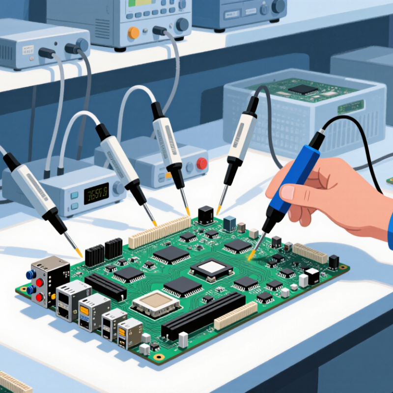
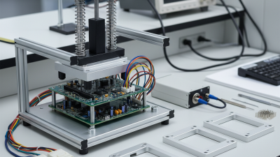
Helps generate or manage test programs, map test points, define measurements, and analyze production test results. |
Open circuits, shorts, incorrect component values, missing components, and some assembly faults that can be accessed electrically. |
ICT tester, fixture or probe access, board connectivity data, and component information. |
Coverage depends on physical access and test-point design. Fixture costs and setup can be significant, especially for low-volume production. |
| Flying Probe Test |
Creates or edits probe sequences and test programs, selects accessible test points, and records electrical measurements. |
Opens, shorts, continuity problems, and selected component or electrical-value faults. |
Flying-probe equipment, board CAD or netlist data, and accessible probe locations. |
Usually avoids a dedicated fixture, but testing may be slower than fixture-based ICT. Limited access can reduce coverage. |
| Boundary-Scan Test |
Supports test-vector creation, device-chain setup, board-level test sequencing, and analysis of scan results when compatible devices are present. |
Some interconnect faults between scan-capable devices, including selected opens and shorts, and certain device-level logic issues. |
Boundary-scan-capable devices, access to the scan chain, device description data, and a compatible test controller. |
Coverage is limited by device support, chain access, and board design. It does not replace all analog, power, or functional tests. |
| Functional Test |
Runs or manages test sequences, controls instruments, checks measured outputs against limits, and logs pass/fail results. |
System-level behavior problems, incorrect signal response, communication failures, and faults that appear only when the board is powered or operating. |
A powered test setup, suitable fixtures or connections, instruments, and defined operating conditions and acceptance limits. |
Test quality depends on scenario coverage and realistic operating conditions. A passing result does not guarantee long-term reliability. |
| Continuity and Insulation Testing |
Defines test connections and limits, coordinates measurements, and stores continuity or insulation-resistance results. |
Broken conductive paths, unintended connections, and inadequate insulation between selected conductors. |
Electrical test instruments, probe or fixture access, and specified test voltage and acceptance limits. |
Only evaluates the paths and conditions included in the test plan; it does not assess all component functions or assembly quality. |
| Test Data Analysis and Traceability |
Combines test logs, associates results with board or batch identifiers, tracks trends, and highlights recurring failure patterns. |
Process drift, repeated defect patterns, unusually high failure rates, and gaps in production test records. |
Consistent test-result data, identifiers, timestamps, and agreed data formats from inspection or test stations. |
Analysis quality depends on accurate, comparable input data. Trend analysis alone does not identify the physical root cause. |